纺织学报 ›› 2023, Vol. 44 ›› Issue (09): 197-204.doi: 10.13475/j.fzxb.20230101101

• 机械与器材 • 上一篇    下一篇

棉纺精梳机分离罗拉连杆驱动机构动力学仿真及有限元分析

冯清国1, 巫鳌飞2, 任家智1,3(), 陈宇恒1   

  1. 1.中原工学院, 河南 郑州 450007
    2.盛美半导体设备(上海)股份有限公司, 上海 201203
    3.先进纺织装备技术省部共建协同创新中心, 河南 郑州 450007
  • 收稿日期:2023-01-05 修回日期:2023-06-16 出版日期:2023-09-15 发布日期:2023-10-30
  • 通讯作者: 任家智(1959—),男,教授,硕士。主要研究方向为棉纺精梳关键技术。E-mail:rjzhi@163.com
  • 作者简介:冯清国(1985—),男,讲师,硕士。主要研究方向为纺纱设备与工艺技术。

Dynamic simulation and finite element analysis of detaching roller linkage drive mechanism for cotton comber machines

FENG Qingguo1, WU Aofei2, REN Jiazhi1,3(), CHEN Yuheng1   

  1. 1. Zhongyuan Institute of Technology, Zhengzhou, Henan 450007, China
    2. Shengmei Semiconductor Equipment (Shanghai) Co., Ltd., Shanghai 201203, China
    3. Collaborative Innovation Center for Advanced Textile Equipment Technology, Zhengzhou, Henan 450007, China
  • Received:2023-01-05 Revised:2023-06-16 Published:2023-09-15 Online:2023-10-30

摘要:

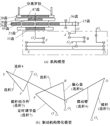
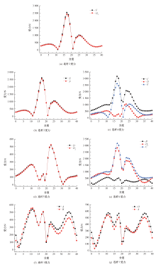
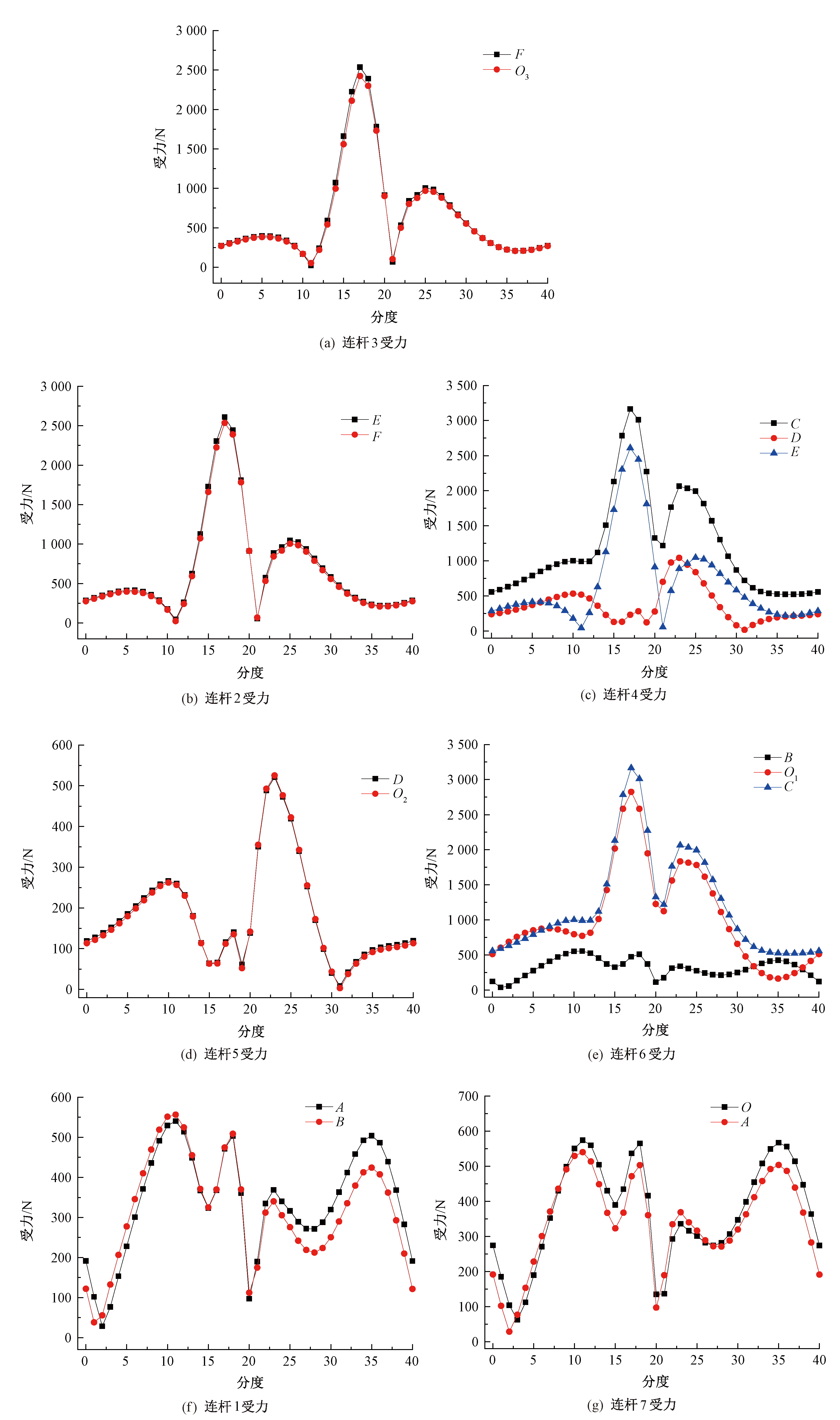
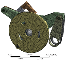
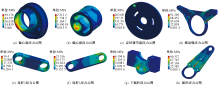
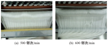
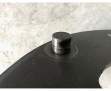
为提高棉纺精梳机的使用寿命及生产运行可靠性,避免精梳机在长期高速运转条件下各零件的疲劳、磨损、断裂等造成的生产事故问题。利用Solidworks软件建立分离罗拉驱动机构三维模型并导入Adams软件分别进行运动学与动力学仿真,得出了不同速度条件下分离罗拉驱动机构各零件铰接点在一个运动周期内的受力分布曲线;利用Ansys Workbench软件对各零件赋予材料属性并进行有限元仿真,得到各零件在一个运动周期内不同速度下的最大应力。结果表明:当精梳机速度为500钳次/min及以下时,一个运动周期内的分离罗拉驱动机构各零件的最大应力均小于材料的许用应力(400 MPa),材料强度满足生产条件;当精梳机速度依次提高到600和700钳次/min后,定时调节盘的最大应力(415.98 MPa)较500钳次/min时分别增大40.55%和79.1%,超过材料的许用应力(400 MPa),该零件有疲劳、磨损、断裂的风险,易故障停车并造成生产事故。在JSFA588型精梳机上按照零件设计要求进行了制造、装配及生产试验,进一步验证了仿真结果的有效性。

关键词: 棉纺, 精梳机, 分离罗拉连杆驱动机构, 铰接点受力, 零件强度, 动力学仿真, 有限元分析

Abstract:

Objective This research aims to improve the long-lasting service and the reliability of the comber machine in cotton spinning. The mechanism of each part of the detaching roller at different velocities was analyzed to solve the problems caused by the fracture of the linkage parts of the detaching roller when working at a high velocity.

Method The first part of the research was focused on the dynamic simulations of the linkage gear of detaching roller based on the JSFA588 comber machine using a finite element (FE) analysis method. The three-dimensional (3-D) model of the linkage gear was established using SolidWorks software and then imported into Adams software. The curves of the force distribution of the linkage points at different velocities in a motion cycle were studied. The second part of this research concentrated on the FE analysis of the stress of each part of the linkage gear using Ansys Workbench software. The material properties of 45-carbon steel were assigned to the FE models and the maximum stress of each part at different velocities in a motion cycle was analyzed.

Results The change tendency of force in each part is the same in a motion cycle, but due to the existence of inertial force, the magnitude of force at the same index is different (Tab. 1). The peak force on each part increases with the speed of the comber machine (Tab. 2). The maximum stress of the eccentric sleeve was 66.565 MPa at 500 nippers/min (Fig. 4(a)); the maximum stress of the eccentric seat was 2.599 2 MPa ( Fig.4(b)); the maximum stress of the timing adjustment disc was 295.96 MPa (Fig. 4(c)); the maximum stress of the swing arm was 102.68 MPa, which is located at its lower end face (Fig. 4(d)); the maximum stress of linkage 2 was 38.667 MPa (Fig. 4(e)); the maximum stress of linkage 1 was 24.187 MPa (Fig. 4(f)); the maximum stress of the lower rocker, located at the round hole articulated with the linkage 1 was 4.718 7 MPa (Fig. 4(g)); and the maximum stress of the rocker was 101.62 MPa (Fig. 4(h)). All of the maximum stresses of the eccentric sleeve, eccentric seat, timing adjustment disc, swing arm, linkage gear 1, linkage gear 2, lower joystick and rocker were less than the allowable stress (400 MPa) in a motion cycle when the velocity of the comber was smaller than 500 nippers/min. The material strength of each part of the linkage gear of detaching roller was suitable for work. The maximum stress of the timing adjustment disc which was 415.98 MPa increased by 40.55% and 79.1%, respectively when the velocity of the comber was set to 600 nippers/min and 700 nippers/min compared to 500 nippers/min. The results showed that it has exceeded the allowable stress (400 MPa), which would lead to the fracture of each part of the linkage gear. Consequently, the comber machine was prone to be shut down. The tests were carried out according to the parametric requirements of the FE analysis on the JSFA588 comber machine, and the feasibility of the parameters was further verified (Tab. 6, Fig. 5 and Fig. 6).

Conclusion The influence of the device strength must be taken into account when the material property was confirmed. Conversely, in order to continue to increase the velocity of the comber machine, it is necessary to balance the influence of the material properties of each part and the cost.

Key words: comber machine, detaching roller linkage drive mechanism, hinge point force, part strength, kinetic simulation, finite element analysis

中图分类号: 

  • TS112.2

图1

分离罗拉平面连杆驱动机构模型及其简化模型"

表1

400 钳次/min时各零件在铰接处的最大受力值及对应的分度"

连杆名称 受力点 最大受力值/N 分度
摇杆结合件
(连杆3)
O3 2 436.23 16.20
F 2 547.36 16.20
连杆2 F 2 547.36 16.20
E 2 618.48 16.20
摆动臂
(连杆4)
E 2 618.48 16.20
C 3 183.44 16.30
D 1 048.39 21.80
摇杆(连杆5) O2 528.34 21.80
D 524.20 21.80
偏心套
(连杆6)
O1 2 824.04 16.10
B 558.33 10.10
C 3 183.44 16.30
连杆1 A 540.67 34.90
B 558.33 10.10
定时调节盘
(连杆7)
O 574.78 35.00
A 540.67 34.90

图2

速度在400 钳次/min时各零件受力"

表2

不同速度下连杆最大受力值及对应的分度"

连杆 铰接
不同速度下的最大受力值/N 分度
400钳次/
min
500钳次/
min
600钳次/
min
700钳次/
min
连杆3 O3 2 436.23 4 153.22 5 983.36 8 146.63 16.20
F 2 547.36 4 332.76 6 238.74 8 491.63 16.20
连杆2 F 2 547.36 4 332.76 6 238.74 8 491.63 16.20
E 2 618.48 4 453.18 6 410.14 8 723.26 16.20
连杆4 E 2 618.48 4 453.18 6 410.14 8 723.26 16.20
C 3 183.44 5 239.66 7 522.93 10 221.79 16.30
D 1 048.39 1 993.24 2 906.38 3 985.34 21.80
连杆5 O2 528.34 1 000.87 1 456.98 1 995.90 21.80
D 524.20 996.62 1 453.19 1 992.67 21.80
连杆6 O1 2 824.04 4 822.04 6 907.32 9 372.16 16.10
B 558.33 797.94 1 148.55 1 563.01 10.10
C 3 183.44 5 239.66 7 522.93 10 221.79 16.30
连杆1 A 540.67 778.97 1 112.54 1 506.76 34.90
B 558.33 797.94 1 148.55 1 563.01 10.10
连杆7 O 574.78 846.66 1 185.91 1 587.21 35.00
A 540.67 778.97 1 112.54 1 506.76 34.90

表3

各连杆铰接点受力峰值增加率"

铰接点 不同速度下受力峰值增加率/%
500钳次/min 600钳次/min 700钳次/min
O3 70.48 145.60 234.39
F 70.09 144.91 233.35
E 70.07 144.8 233.14
C 64.59 136.31 221.09
D 90.12 177.22 280.13
O2 89.44 175.77 277.78
O1 70.75 144.59 231.87
B 42.92 105.71 179.94
O 44.07 105.77 176.14
A 47.30 106.32 178.68

图3

分离罗拉连杆驱动机构有限元模型"

表4

连杆机构零件材料属性"

材料 密度/
(kg·m-3)
屈服强
度极限
σs/MPa
抗拉强
度极限
σb/MPa
抗剪
模量/
(N·m2)
弹性
模量/
(N·m2)
泊松比
45碳素
结构钢
7 890 355 600 8.23×
1010
2.09×
1011
0.269

图4

速度为500钳次/min时连杆机构各零件应力云图"

表5

不同速度下各零件最大应力"

零件名称 不同速度下的最大应力/MPa
500钳次/min 600钳次/min 700钳次/min
偏心套 66.57 65.14 137.89
偏心座 2.60 4.27 5.38
定时调节盘 295.96 415.98 530.06
摆动臂 102.68 102.68 102.68
连杆2 38.67 51.12 67.27
连杆1 24.19 24.19 24.19
下摇杆 4.72 5.42 11.66
摇杆 101.62 101.62 101.62

表6

不同速度下精梳机驱动机构振动情况"

速度/
(钳次·min-1)
车头加速度/
(m·s-2)
车头速度/
(mm·s-1)
车头位移/μm
500 11.74 4.31 57.83
600 12.75 4.84 68.79

图5

精梳机不同速度时精梳棉网状况"

图6

定时调节盘圆孔位置销轴受损情况"

[1] 贾国欣, 任家智, 李佳. 棉纺精梳机分离罗拉的运动建模及优化[J]. 河南工程学院学报(自然科学版), 2018, 30(1):13-19.
JIA Guoxin, REN Jiazhi, LI Jia. The motion modeling and optimization of detaching roller on cotton comber[J]. Journal of Henan Institute of Engineer-ing (Natural Science Edition), 2018, 30(1):13-19.
[2] 王振宇, 李新荣, 蒋秀明, 等. 棉精梳机分离罗拉运动位移研究[J]. 纺织器材, 2017, 44(3):14-17.
WANG Zhenyu, LI Xinrong, JIANG Xiuming et al. Research on motion displacement of detached roller of the cotton comber[J]. Textile Accessories, 2017, 44(3):14-17.
[3] 徐子静, 王娟, 李明海. 基于ANSYS Workbench的连杆强度校核及模态分析[J]. 铁道机车与动车, 2019(8):1-5,19.
XU Zijing, WANG Juan, LI Minghai. Strength check and modal analysis of connecting rod based on ansys workbench[J]. Railway Locomotive and Motor Car, 2019(8):1-5,19.
[4] 方兴未. 水力破拆机器人新型工作装置仿真及有限元分析[D]. 马鞍山: 安徽工业大学, 2019:30-41.
FANG Xingwei. Simulation and finite element analysis of new working device of hydraulic demolition robot[D]. Ma'anshan: Anhui University of Technology, 2019:30-41.
[5] 袁俊凇, 孔啸, 孙嘉继, 等. 铝合金薄壁件铣削加工变形有限元分析[J]. 现代制造工程, 2011(11):96-100.
YUAN Junji, KONG Xiao, SUN Jiaji, et al. Finite element analysis for milling deflection of thin-walled aluminum parts[J]. Modern Manufacturing Engineering, 2011(11):96-100.
[6] 李金键. 棉纺精梳机钳板驱动系统力学性能分析[D]. 郑州: 中原工学院, 2021:41-53.
LI Jinjian. Mechanical property analysis about nipper drive system in cotton comber[D]. Zhengzhou: Zhongyuan University of Technology, 2021:41-53.
[7] 杨可桢, 程光蕴, 李仲. 机械设计基础[M]. 北京: 高等教育出版社, 2006:111-127.
YANG Kezhen, CHENG Guangyun, LI Zhong. Fundamentals of mechanical design[M]. Beijing: Higher Education Press, 2006:111-127.
[8] 任家智, 巫鳌飞, 贾国欣, 等. 棉纺精梳机分离罗拉动力学分析[J]. 棉纺织技术, 2020, 48(4):7.
REN Jiazhi, WU Aofei, JIA Guoxin, et al. Analyses on dynamics of detaching roller in cotton spinning comber[J]. Cotton Textile Technology, 2020, 48(4):7.
[9] 巫鳌飞. 精梳机分离罗拉驱动连杆强度分析[D]. 郑州: 中原工学院, 2020:25-58.
WU Aofei. Strength analysis of connecting rod driven by detaching roller of comber[D]. Zhengzhou: Zhongyuan University of Technology, 2020:25-58.
[10] 夏链, 张进, 韩江, 等. 八连杆机械式压力机动力学分析[J]. 锻压技术, 2012, 37(4):158-161.
XIA Lian, ZHANG Jin, HAN Jiang, et al. Kinematics analysis of eight-link mechanical press[J]. Forging & Stamping Technology, 2012, 37(4):158-161.
[11] 刘俊利, 徐建, 孔秀平. 基于ADAMS的采煤机虚拟样机建立与运动学仿真[J]. 煤炭技术, 2018, 37(5):222-224.
LIU Junli, XU Jian, KONG Xiuping. Virtual prototype modeling and kinematics simulation of shearer based on ADAMS[J]. Coal Technology, 2018, 37(5):222-224.
[1] 陈宇恒, 高卫东, 任家智. 精梳机分离牵伸力在线检测与规律分析[J]. 纺织学报, 2022, 43(08): 1-6.
[2] 余玉坤, 孙玥, 侯珏, 刘正, 易洁伦. 单层服装间隙量的动态有限元模型构建与仿真[J]. 纺织学报, 2022, 43(04): 124-132.
[3] 骆晓蕾, 刘琳, 姚菊明. 纯生物质纤维素气凝胶的制备及其阻燃性能[J]. 纺织学报, 2022, 43(01): 1-8.
[4] 梁灼, 贾国欣, 任家智, 李金键. 棉纺精梳机钳板的变形及其应力分析[J]. 纺织学报, 2021, 42(12): 145-150.
[5] 权震震, 王亦涵, 祖遥, 覃小红. 多曲面喷头静电纺射流形成机制与成膜特性[J]. 纺织学报, 2021, 42(09): 39-45.
[6] 卢俊, 王富军, 劳继红, 王璐, 林婧. 复合载荷下不同结构编织人工韧带的有限元分析[J]. 纺织学报, 2021, 42(08): 84-89.
[7] 周濛濛, 蒋高明, 高哲, 郑培晓. 纬编衬经衬纬管状织物增强复合材料研究进展[J]. 纺织学报, 2021, 42(07): 184-191.
[8] 李金键, 任家智, 梁灼, 贾国欣. 棉纺精梳机钳板摆轴的动力学分析[J]. 纺织学报, 2021, 42(06): 160-165.
[9] 吕常亮, 郝志远, 陈慧敏, 张慧乐, 岳晓丽. 基于均匀化理论的小变形纬编针织物线圈形态有限元分析[J]. 纺织学报, 2021, 42(03): 21-26.
[10] 封端佩, 商元元, 李俊. 三维四向和五向编织复合材料冲击断裂行为的多尺度模拟[J]. 纺织学报, 2020, 41(10): 67-73.
[11] 武鲜艳, 申屠宝卿, 马倩, 金利民, 张威, 谢胜. 球形弹体冲击下三维正交机织物结构破坏机制有限元分析[J]. 纺织学报, 2020, 41(08): 32-38.
[12] 戴鑫, 李晶, 陈晨. 镀铜碳纤维丝束细观耐磨性的有限元仿真模拟[J]. 纺织学报, 2020, 41(06): 27-35.
[13] 刘立东, 李新荣, 杨海鹏, 卜兆宁. 棉精梳机分离罗拉伺服驱动研究[J]. 纺织学报, 2020, 41(01): 158-164.
[14] 杨海鹏, 李新荣, 吕鹏飞, 王振宇. 采用混合驱动的精梳机分离罗拉传动机构[J]. 纺织学报, 2019, 40(04): 122-128.
[15] 马倩 王可 金利民. 三维角联锁机织复合材料的冲击破坏有限元模拟分析[J]. 纺织学报, 2017, 38(07): 63-68.
Viewed
Full text


Abstract

Cited

  Shared   
  Discussed   
No Suggested Reading articles found!